Get an Instant Quote
Choose a service
- No: This part does not have any export control.
-
Yes: This part is subject to export control regulations such as ITAR, EAR, or
otherwise considered Controlled Unclassified Information (CUI).
- Momentum Optics will only produce these parts with suppliers that have successfully gone through the appropriate registration process.
- Only US Persons will have access to sensitive information regarding this part.
- Your quoted price and lead time may be affected.
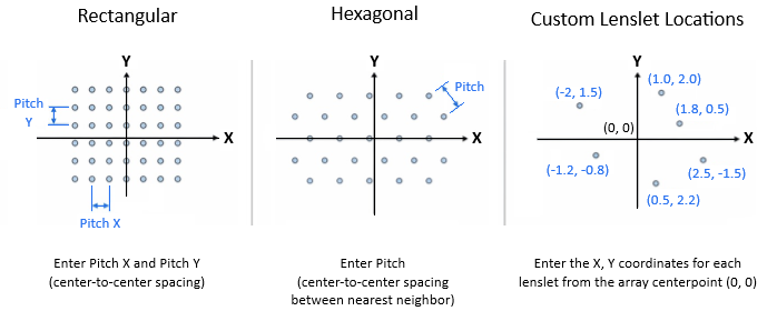
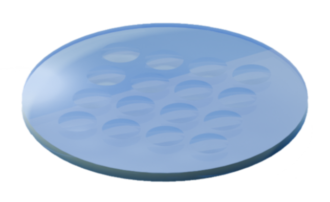
- Rectangular arrays are often simpler for processing, especially if using a traditional rectangular grid.
- Hexagonal lens arrays offer higher fill factors and more uniform light distribution than rectangular arrays, making them better for applications like high-resolution imaging and homogenized illumination.
- Custom Lenslet Locations allows you to specify exactly where you want the lenslets to be. This is the most flexible option, especially useful if you would like a portion of the array area to not include lenslets.
Array Pitch for hexagonal arrays is the distance of a straight line between the midpoints of two lenslets.
| Tier | Lead Time in Weeks |
|---|---|
| Economy | 6 weeks |
| Standard | 4 weeks |
| Accelerated | 2 weeks |
Below are the default values for each tolerance per level. Select a level to apply these values to all tolerances and then modify the individual tolerances in the form as appropriate to your desired precision. Tolerance values below the High Precision level (greater precision) require a Manual Quote to ensure manufacturability and determine price and lead times.
| Predfined Levels | ||||||
|---|---|---|---|---|---|---|
| Attribute | Standard | Precision | High Precision | |||
| Edge Diameter (mm) | +0.0 | -0.1 | +0.00 | -0.05 | +0.000 | -0.025 |
| Center Thickness (mm) | +0.100 | -0.100 | +0.075 | -0.075 | +0.050 | -0.050 |
| Edge Thickness (mm) | +0.100 | -0.100 | +0.05 | -0.05 | +0.025 | -0.025 |
| Irregularity (RMS) (μm) | +0.632 | -0.632 | +0.316 | -0.316 | +0.211 | -0.211 |
| Irregularity (PV) (μm) | +2 | -2 | +1.5 | -1.5 | +1 | -1 |
| Radius of Curvature (mm) | +0.25 | -0.25 | +0.15 | -0.15 | +0.1 | -0.1 |
| Wedge (ETD) (mm) | +0.05 | -0.05 | +0.01 | -0.01 | +0.005 | -0.005 |
| Array Pitch (mm) | +0.050 | -0.050 | +0.025 | -0.025 | +0.010 | -0.010 |
| Flatness (λ) | +λ/2 | -λ/2 | +λ/4 | -λ/4 | +λ/10 | -λ/10 |
| Parallelism (arcseconds) | +180 | -180 | +30 | -30 | +5 | -5 |
These are the materials we regularly stock for manufacturing. If you don't see the material you need, select Other and we can special order it for you. Other materials require a Manual Quote.
| MFG | Name | In Stock | Refractive Index |
|---|---|---|---|
| Corning | 7980 Fused Silica, Standard Grade 0,F (Corning) | Yes | 1.4585 |
| Schott | N-BK7 (Schott) | Yes | 1.5168 |
| Schott | N-SF6 (Schott) | Yes | 1.80518 |
| Schott | N-SF11 (Schott) | Yes | 1.78472 |
| CDGM | JGS1 Fused Silica, Standard Grade (CDGM) | Yes | 1.4585 |
| CDGM | H-K9L (CDGM) | Yes | 1.5168 |
| CDGM | H-ZF13 (CDGM) | Yes | 1.78472 |
| CDGM | H-ZF7LA (CDGM) | Yes | 1.9037 |
| CDGM | H-LaF10L (CDGM) | Yes | 1.7880 |
Please select from this list of common materials. If your part material is not listed, please select Other and enter the name of that material.
| MFG | Name |
|---|---|
| CDGM | F1 (CDGM) |
| CDGM | Fused Silica, Optical grade - JGS1 (CDGM) |
| CDGM | Fused Silica, Optical grade - JGS2 (CDGM) |
| CDGM | H-BaK7 (CDGM) |
| CDGM | H-F4 (CDGM) |
| CDGM | H-FK61 (CDGM) |
| CDGM | H-K50 (CDGM) |
| CDGM | H-K50 (CDGM) |
| CDGM | H-K51A (CDGM) |
| CDGM | H-K9L (CDGM) |
| CDGM | H-LAF3 (CDGM) |
| CDGM | H-LAF50B (CDGM) |
| CDGM | H-LAK2 (CDGM) |
| CDGM | H-LAK51A (CDGM) |
| CDGM | H-LAK52 (CDGM) |
| CDGM | H-LaF10L (CDGM) |
| CDGM | H-LaF4 (CDGM) |
| CDGM | H-LaF50B (CDGM) |
| CDGM | H-LaK10 (CDGM) |
| CDGM | H-LaK50A (CDGM) |
| CDGM | H-LaK51A (CDGM) |
| CDGM | H-LaK52 (CDGM) |
| CDGM | H-LaK5A (CDGM) |
| CDGM | H-LaK7 (CDGM) |
| CDGM | H-QF1 (CDGM) |
| CDGM | H-QF6 (CDGM) |
| CDGM | H-QK3L (CDGM) |
| CDGM | H-TF3L (CDGM) |
| CDGM | H-ZBAF3 (CDGM) |
| CDGM | H-ZBaF20 (CDGM) |
| CDGM | H-ZBaF52 (CDGM) |
| CDGM | H-ZF10 (CDGM) |
| CDGM | H-ZF11 (CDGM) |
| CDGM | H-ZF4 (CDGM) |
| CDGM | H-ZF52A (CDGM) |
| CDGM | H-ZF6 (CDGM) |
| CDGM | H-ZF71 (CDGM) |
| CDGM | H-ZF72A (CDGM) |
| CDGM | H-ZF7LA (CDGM) |
| CDGM | H-ZK10L (CDGM) |
| CDGM | H-ZK2 (CDGM) |
| CDGM | H-ZK3 (CDGM) |
| CDGM | H-ZK50 (CDGM) |
| CDGM | H-ZK6 (CDGM) |
| CDGM | H-ZK9A (CDGM) |
| CDGM | H-ZLAF50D (CDGM) |
| CDGM | H-ZLAF55A (CDGM) |
| CDGM | H-ZLaF50B (CDGM) |
| CDGM | H-ZLaF52 (CDGM) |
| CDGM | H-ZLaF55A (CDGM) |
| CDGM | H-ZLaF68 (CDGM) |
| CDGM | H-ZLaF71 (CDGM) |
| CDGM | H-ZPK1 (CDGM) |
| CDGM | JGS2 (CDGM) |
| CDGM | QF50 (CDGM) |
| CDGM | ZF1 (CDGM) |
| CDGM | ZF13 (CDGM) |
| CDGM | ZF3 (CDGM) |
| Corning | Fused Silica, IR - Corning 7979 (Corning) |
| Corning | Fused Silica, UV - Corning 7980 (Corning) |
| Ohara | NSL51 (Ohara) |
| Ohara | PBH11 (Ohara) |
| Ohara | PBL25 (Ohara) |
| Ohara | PBM22 (Ohara) |
| Ohara | PBM5 (Ohara) |
| Ohara | S-BAH10 (Ohara) |
| Ohara | S-BAH27 (Ohara) |
| Ohara | S-BAL14 (Ohara) |
| Ohara | S-BAL35 (Ohara) |
| Ohara | S-BAL42 (Ohara) |
| Ohara | S-BSL7 (Ohara) |
| Ohara | S-BSM10 (Ohara) |
| Ohara | S-BSM16 (Ohara) |
| Ohara | S-BSM2 (Ohara) |
| Ohara | S-BSM4 (Ohara) |
| Ohara | S-FPL51 (Ohara) |
| Ohara | S-FSL5 (Ohara) |
| Ohara | S-LAH51 (Ohara) |
| Ohara | S-LAH53 (Ohara) |
| Ohara | S-LAH55 (Ohara) |
| Ohara | S-LAH58 (Ohara) |
| Ohara | S-LAH64 (Ohara) |
| Ohara | S-LAH65 (Ohara) |
| Ohara | S-LAH66 (Ohara) |
| Ohara | S-LAH71 (Ohara) |
| Ohara | S-LAL12 (Ohara) |
| Ohara | S-LAL14 (Ohara) |
| Ohara | S-LAL18 (Ohara) |
| Ohara | S-LAL54 (Ohara) |
| Ohara | S-LAL7 (Ohara) |
| Ohara | S-LAL8 (Ohara) |
| Ohara | S-LAL9 (Ohara) |
| Ohara | S-LAM2 (Ohara) |
| Ohara | S-LAM7 (Ohara) |
| Ohara | S-NBM51 (Ohara) |
| Ohara | S-NPH1 (Ohara) |
| Ohara | S-NPH2 (Ohara) |
| Ohara | S-NSL5 (Ohara) |
| Ohara | S-NSL5 (Ohara) |
| Ohara | S-PHM52 (Ohara) |
| Ohara | S-TIH1 (Ohara) |
| Ohara | S-TIH10 (Ohara) |
| Ohara | S-TIH11 (Ohara) |
| Ohara | S-TIH4 (Ohara) |
| Ohara | S-TIH53 (Ohara) |
| Ohara | S-TIH6 (Ohara) |
| Ohara | S-TIL1 (Ohara) |
| Ohara | S-TIL6 (Ohara) |
| Ohara | S-TIM2 (Ohara) |
| Ohara | S-TIM28 (Ohara) |
| Ohara | S-TIM35 (Ohara) |
| Schott | B270 (Schott) |
| Schott | BOROFLOAT33 (Schott) |
| Schott | D263 (Schott) |
| Schott | F5 (Schott) |
| Schott | LF5 (Schott) |
| Schott | LLF1 (Schott) |
| Schott | N-BAF10 (Schott) |
| Schott | N-BAK4 (Schott) |
| Schott | N-BK7 (Schott) |
| Schott | N-F2 (Schott) |
| Schott | N-FK5 (Schott) |
| Schott | N-FK51A (Schott) |
| Schott | N-FK58 (Schott) |
| Schott | N-K5 (Schott) |
| Schott | N-KF9 (Schott) |
| Schott | N-LAF2 (Schott) |
| Schott | N-LAF21 (Schott) |
| Schott | N-LAF33 (Schott) |
| Schott | N-LAF34 (Schott) |
| Schott | N-LAF7 (Schott) |
| Schott | N-LAK12 (Schott) |
| Schott | N-LAK14 (Schott) |
| Schott | N-LAK22 (Schott) |
| Schott | N-LAK33A (Schott) |
| Schott | N-LAK34 (Schott) |
| Schott | N-LAK7 (Schott) |
| Schott | N-LAK8 (Schott) |
| Schott | N-LAK9 (Schott) |
| Schott | N-LASF31A (Schott) |
| Schott | N-LASF41 (Schott) |
| Schott | N-LASF43 (Schott) |
| Schott | N-LASF44 (Schott) |
| Schott | N-LASF9 (Schott) |
| Schott | N-PK51 (Schott) |
| Schott | N-PK52A (Schott) |
| Schott | N-PSK53A (Schott) |
| Schott | N-SF1 (Schott) |
| Schott | N-SF10 (Schott) |
| Schott | N-SF11 (Schott) |
| Schott | N-SF15 (Schott) |
| Schott | N-SF2 (Schott) |
| Schott | N-SF4 (Schott) |
| Schott | N-SF5 (Schott) |
| Schott | N-SF57 (Schott) |
| Schott | N-SF6 (Schott) |
| Schott | N-SF8 (Schott) |
| Schott | N-SK10 (Schott) |
| Schott | N-SK16 (Schott) |
| Schott | N-SK2 (Schott) |
| Schott | N-SK4 (Schott) |
| Schott | N-SK5 (Schott) |
| Schott | SF11 (Schott) |
| Schott | SF2 (Schott) |
| Schott | SK12 (Schott) |
| Schott | Zerodur (Schott) |
| Other | Soda Lime (Other) |
Edge Diameter is the length from top to bottom if looking at the optic from the side. The Edge Diameter is the outer dimension of the part sometimes referred to as the "mechanical diameter" or "outside diameter."
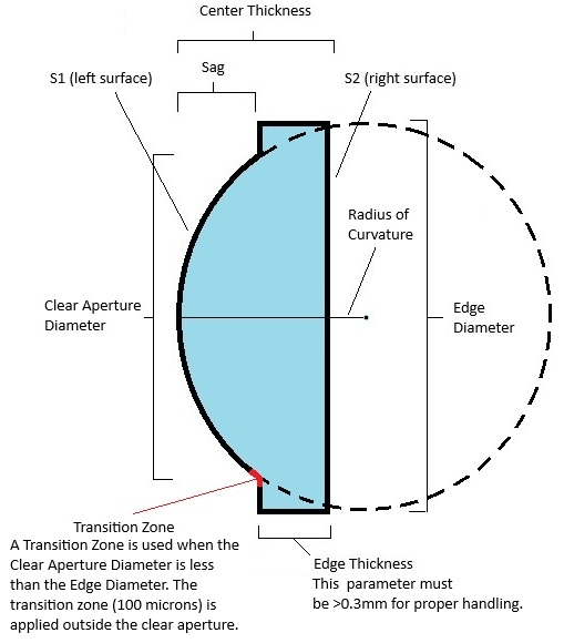
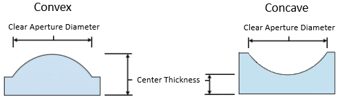
Center thickness is the depth at the centerpoint of the optic diameter.
Edge thickness is the depth along the edge of the physical part. If this varies, enter the maximum thickness.
Radius of Curvature is the radius of a circle that would end at the edge of the curved, outer surface of an optic.
Radius of Curvature Tolerance is the acceptable deviation from radius of curvature along the optic surface.
Irregularity (RMS - Root Mean Square) is the deviation of the surface from the ideal or prescribed surface. The irregularity is sometime referred to as the "Figure Error."
Irregularity (PV - Peak-to-Valley) is the deviation of the surface from the ideal or prescribed surface. The irregularity is sometime referred to as the "Figure Error."
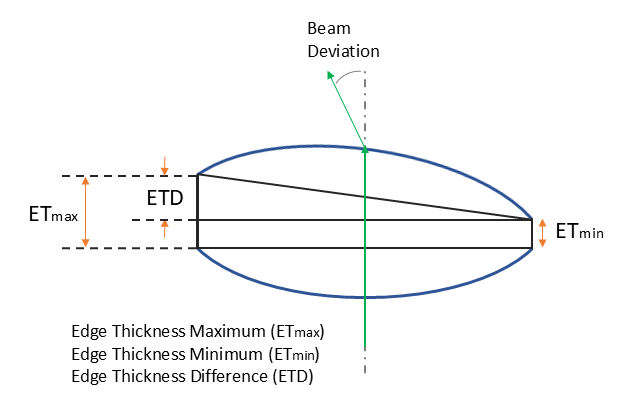
Wedge defines the lack of parallelism between two optical surfaces. It can be characterized as Total Indicator Runout (TIR) or Edge Thickness Difference (ETD). We measure ETD defined as the difference between the maximum and minimum edge thickness.
| AR Coatings | ||
| Coating Name | Wavelength Range | Reflectance |
|---|---|---|
| UV | 245 - 400 nm | Ravg < 0.5% |
| A | 400 - 700 nm | Ravg < 0.5% |
| AB | 400 - 1,000 nm | Ravg < 1.0% |
| B | 650 - 1,050 nm | Ravg < 0.5% |
| C | 1,050 - 1,700 nm | Ravg < 0.5% |
| D | 1,650 - 3,000 nm | Ravg < 1.0% |
| E1 | 2,000 - 5,000 nm | Ravg < 1.5% |
| E2 | 3,000 - 5,000 nm | Ravg < 0.5% |
| E3 | 4,500 - 7,500 nm | Ravg < 1.0% |
| E4 | 2,000 - 13,000 nm | Ravg < 5.0% |
| F1 | 7,000 - 12,000 nm | Ravg < 1.0% |
| F2 | 8,000 - 12,000 nm | Ravg < 0.5% |
| HR Coatings | ||
| Coating Name | Wavelength Range | Reflectance |
| EH1 | 350 - 400 nm | Ravg > 99% |
| EH2 | 450 - 650 nm | Ravg > 99% |
| EH3 | 750 - 1,050 nm | Ravg > 99% |
| FH1 (UV Enhanced Al) | 250 - 450 nm | Ravg > 87% |
| GH1 (Protected Al) | 450 - 20,000 nm | Ravg > 88% (450 nm-2,000 nm), Ravg > 95% (2,000 nm - 20,000 nm) |
| UAG1 (Ultrafast Enhanced Ag) | 750 - 1,000 nm | Ravg,S > 99.0%, Ravg, P > 98.0% |
| PAG1 (Protected Ag) | 450 - 20,000 nm | Ravg > 97% (450 nm-2,000 nm), Ravg > 95% (2,000 nm - 20,000 nm) |
| MH1 (Protected Au) | 800 - 20,000 nm | Ravg > 97% |
| MH3 (Bare Au) | 800 - 20,000 nm | Ravg > 97% |
Clear Aperture Diameter is the optical diameter or active region of the optic where specifications are met.
Clear Aperture Diameter Tolerance is the acceptable deviation from clear aperture diameter along the optic surface.
| Surface Roughness | Threshold |
|---|---|
| Standard quality | < 5 nm |
| High quality | < 2 nm |
| Superpolished | < .5 nm |
Scratch/Dig is a visual surface quality rating per MIL-PRF-13830B. The first number limits scratch width; the second limits dig (pit) diameter-smaller numbers mean higher cosmetic quality. This is verified by visual comparison using a Thorlabs MOTP-MILB Scratch-Dig Panel.
Select the urgency we should place on building your optic.
Optionally select additional inspections you would like us to perform. The Standard inspection is included with all parts and services we provide.
Optionally select certificates to be printed and included with your part.
Tolerances +/- define allowable deviation in physical dimensions, ensuring components meet strict performance requirements.
Part/Edge Diameter Tolerance +: this tolerance is particularly critical to ensure the part will fit in a barrel or other housing component. It uses decimals of precision. For example, 0.0 allows up to 90 microns deviation, 0.00 allows up to 9 microns and 0.000 only allows less than a single micron deviation.
Part/Edge Diameter Tolerance -: how much deviation under the diameter is allowed.
Tolerances +/- define allowable deviation in physical dimensions, ensuring components meet strict performance requirements.
Center Thickness Tolerance: how much deviation is allowed above/below the specified center thickness parameter.
Tolerances +/- define allowable deviation in physical dimensions, ensuring components meet strict performance requirements.
Radius of Curvature Tolerance: how much deviation is allowed above/below the specified radius of curvature parameter.
This is the physical shape of the part: Circular, Elliptical, Rectangular, or Other. Other shapes require a Manual Quote to ensure manufacturability and determine price and lead times.
Describe the physical shape of the outer part that includes the lens array (i.e. Triangular, Trapezoidal, Hexagonal, Irregular).
Outer diameter of the physical part.
Enter the width (X) of the physical part.
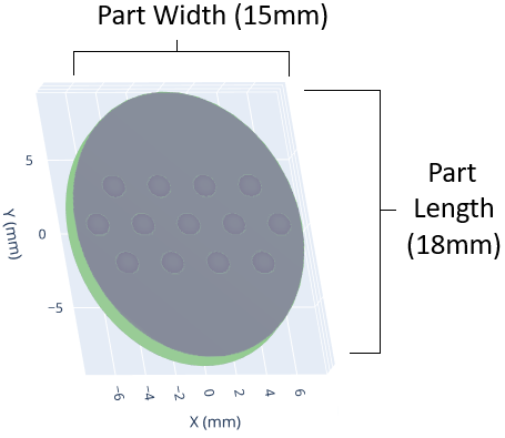
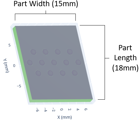
Enter the length (Y) of the physical part.
Distance in X between midpoints of lenslets in a rectangular alignment/configuration.
Distance in Y between midpoints of lenslets in a rectangular alignment/configuration.
Tolerances +/- define allowable deviation in physical dimensions, ensuring components meet strict performance requirements.
Array Pitch Tolerance: how much deviation is allowed above/below the specified pitch - distance between lenslet midpoints.
Thickness at the center point of each lenslet in an array.
Maximum thickness of the part along the outer edge boundaries.
If the edge thickness is not consistent along the entire part, enter the maximum thickness of the outer the edge.

Clear aperture percentage of the part being coated. About 5% of the optic is required for holding the part in the coating planetarium and will not be completely coated.
Specify in percentage decimal the percentage of the optic requiring coating.
Tolerances +/- define allowable deviation in physical dimensions, ensuring components meet strict performance requirements.
Part Dimensional Tolerance: tolerance for the physical part width, length, or diameter given.
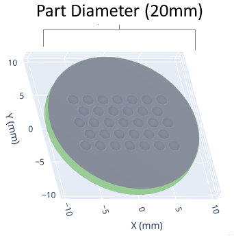
The shape of the boundary around the set of lenslets that comprise the array: Circular, Elliptical, Rectangular, or Other. This shape can differ from the outer part shape and will define the outer limits of the part where lenslets will be. We will fill this array shape with lenslets that fit within its dimensions, based on the Array Configuration (lenslet alignment), selected below.
In the diagram below the physical part is rectangular with a circular array within the part.
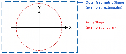
NOTE: To specify custom lenslet locations use the same shape as the physical part, then select Custom Lenslet Locations for the Array Configuration below.
Describe the boundary shape of the array. This is the shape that the set of lenslets makes within the physical part.
For circular arrays, enter the diameter across the array of lenslets. No lenslets should be outside of the array boundaries.
For elliptical or rectangular arrays, enter the array width. Be sure to use the correct width of the array oriented within the outer part shape.
For elliptical or rectangular arrays, enter the array length. Be sure to use the correct length of the array oriented within the outer part shape.
This describes how lenslets are aligned or "packed" into the array on the part. For Rectangular or Hexagonal arrays, the lenslets will be fit automatically to the array shape boundaries.
To manually enter the coordinates for each lenslet, select Custom Lenslet Locations and add the lenslets individually. This option is available when you don't want lenslets to fill the entire array area.
With Rectangular or Hexagonal arrays, you enter the pitch and it is applied to all lenslets. For Custom Lenslet Locations, no pitch is given, as you are entering each lenslet midpoint.
Tolerances +/- define allowable deviation in physical dimensions, ensuring components meet strict performance requirements.
Lenslet Location Tolerance: tolerance for the specific coordinates of the centerpoint for each of the lenslets.
Enter specific lenslet coordinates for arrays that are not fully packed. Enter the X and Y coordinates for the centerpoint of each lenslet. The center of the array shape is (x=0, y=0).
Enter as many lenslets as you would like within the array size. The lenslets cannot overlap. The diameter/dimension of the individual lenslet is given by the S1 Clear Aperture value.
Thickness of the part, with flats, it will be a uniform thickness.
Tolerances +/- define allowable deviation in physical dimensions, ensuring components meet strict performance requirements.
Flat Window Thickness Tolerance: how much deviation is allowed above/below the specified part thickness parameter.
Flatness is the surface deviation from a perfect plane. Flatness is measured by interferometry and may be referred to in units of waves.
Parallelism is a measure of how close the front surface is to being perfectly parallel to the back surface. If a window is not parallel, it acts like a wedge, which will bend (deviate) the light passing through it. Parallelism is measured in units of arcseconds.
Standard Step file (.stp) containing geometric part information.